Arduino based Johnson KW Matchbox Autotuner
I **LOVE** the old Johnson KW Matchbox. It is a great balanced tuner. It is a great bandpass filter. It will tune about anything. The problem is that they are fairly high-Q and requires tuning even with small frequency changes, especially on 80 meters. 80 meters is a large band in terms of percentage bandwidth, and the small value of capacitors in the matchbox yields very high Q.
So... I thought, what about putting stepper motors on a Johnson KW Matchbox and controlling it with an Arduino. The first step was to mount stepper motors, which I did by mounting them on the back of the chassis. I also arranged an opt coupler, which is interrupted by a swinging arm such that the ‘home’ position can be found.


(Hint: for more detail download the images by clicking on them.)
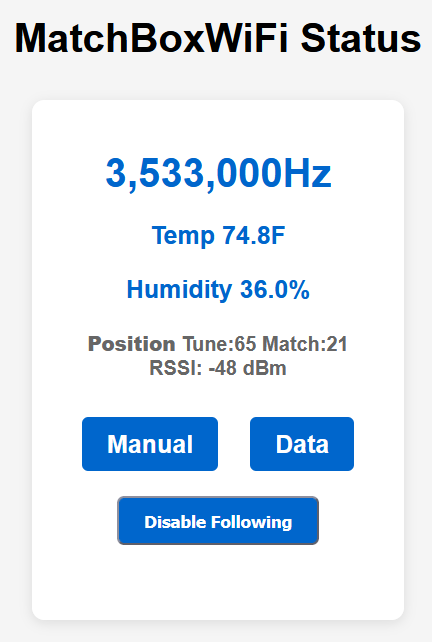
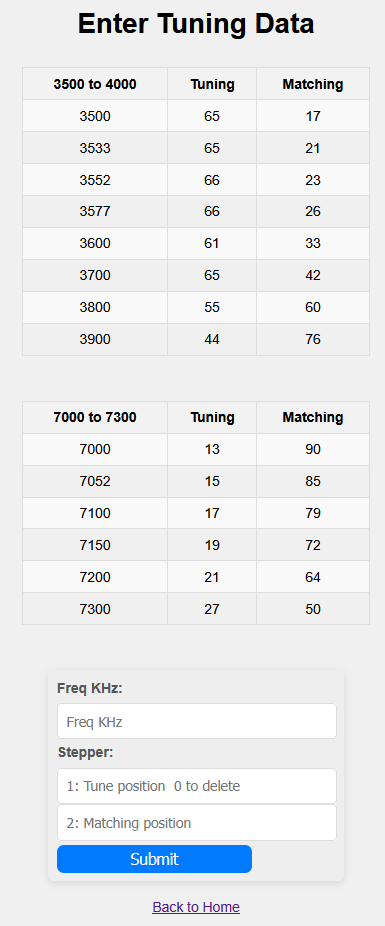
I originally had the Matchbox installed and operating in what I call pure "Table Mode" where the tuner has table and the stepper motors tune to a position based on the table that was hard coded. This is done by reading Icom CI-V frequency messages and going to a look up table to determine where to set the knobs. It is only as accurate as the table. I first implemented the code on a Arduino Uno.
The problem with a table based approach is that if the feeder is wet, tuning will not be the same as when it is raining, but it works quite well when things are dry and stable.
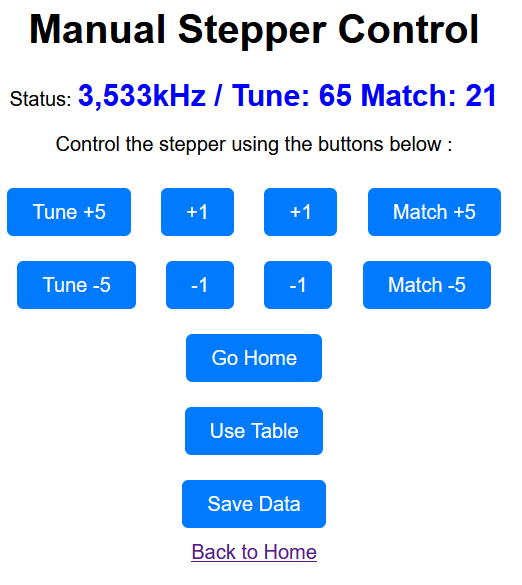
When the tuner is not tuning, the operator has full control over the tuner by turning the knobs, so it still operates as a normal Johnson KW Matchbox.
Watch a video showing how it works
The motor drivers are done through an I2C interface, using an 8 bit I/O expander, PCF8575N. For each motor, there are two lines that define the phase, and one line that is an enathe motor . The other three lines are used to enable power to the LED in the two opto-couplers and two sense transistors are brought back to the controller to mark where home is located. The N channel FETS for the motor drivers must easily be able to handle the current of the motors. NOR gates should have enough drive current to operate the power FETs, suggest HC or HCT parts.
Rough schematic
This was done about 15 years ago, since then there are much better stepper motor controller ICs, Including Arduino shields, like the WWZMDiB CNC Shield V3 Engraving Machine Expansion Board A4988 Driver Expansion Board for Arduino. But, having already built a working controller, I used that.